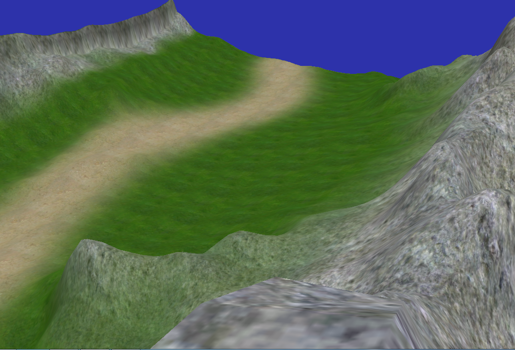
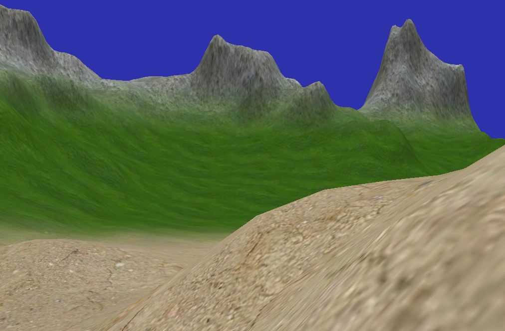
地形模拟演示Demo
地形渲染的首先是创建一个三角网络平面,然后调整平面顶点的y高度值,模拟地面的山丘和山谷,最后再绘制贴图效果。本文首先介绍如何生成三角网络平面。然后介绍如何通过高度图调整平面高度。以及使用BlendMap和3种材质绘制贴图效果的方法。最后演示如何调整摄像机位置和移动速度,在地面上行走。
生成三角网络平面
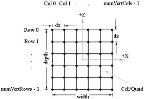
一个m*n个顶点的平面由2*(m-1)*(n-1)个三角形组成。行列的宽度分别为dx,dz。
首先生成顶点坐标,假设平面的中心在坐标原点。左上角的顶点坐标就为(-(m-1)*dx, 0, (n-1)*dz)。再生成索引,每个循环迭代中生成一个四边形的两个三角形的6个索引信息。如图所示。
∆ABC = {i·m+ j, i·m+j+1, (i+1)·m+ j}
∆CBD = {(i+1)·m+ j, i·m+ j+1, (i+1)·m+ j+1}
然后使用生成的顶点坐标和索引创建ID3DXMesh对象。顶点的Y值从下文介绍的高度图获取。顶点法向量由D3DXComputeNormals计算。完整代码如下。
void Terrain::GenTriGrid(int numVertRows, int numVertCols,
	float dx, float dz,
	const D3DXVECTOR3& center,
	std::vector<D3DXVECTOR3>& verts,
	std::vector<DWORD>& indices)
{
	int numVertices = numVertRows*numVertCols;
	int numCellRows = numVertRows-1;
	int numCellCols = numVertCols-1;

	int numTris = numCellRows*numCellCols*2;

	float width = (float)numCellCols * dx;
	float depth = (float)numCellRows * dz;

	//===========================================
	// Build vertices.

	// We first build the grid geometry centered about the origin and on
	// the xz-plane, row-by-row and in a top-down fashion.  We then translate
	// the grid vertices so that they are centered about the specified
	// parameter 'center'.

	verts.resize( numVertices );

	// Offsets to translate grid from quadrant 4 to center of
	// coordinate system.
	float xOffset = -width * 0.5f;
	float zOffset =  depth * 0.5f;

	int k = 0;
	for(float i = 0; i < numVertRows; ++i)
	{
		for(float j = 0; j < numVertCols; ++j)
		{
			// Negate the depth coordinate to put in quadrant four.
			// Then offset to center about coordinate system.
			verts[k].x =  j * dx + xOffset;
			verts[k].z = -i * dz + zOffset;
			verts[k].y =  0.0f;

			// Translate so that the center of the grid is at the
			// specified 'center' parameter.
			D3DXMATRIX T;
			D3DXMatrixTranslation(&T, center.x, center.y, center.z);
			D3DXVec3TransformCoord(&verts[k], &verts[k], &T);

			++k; // Next vertex
		}
	}

	//===========================================
	// Build indices.

	indices.resize(numTris * 3);

	// Generate indices for each quad.
	k = 0;
	for(DWORD i = 0; i < (DWORD)numCellRows; ++i)
	{
		for(DWORD j = 0; j < (DWORD)numCellCols; ++j)
		{
			indices[k]     =   i   * numVertCols + j;
			indices[k + 1] =   i   * numVertCols + j + 1;
			indices[k + 2] = (i+1) * numVertCols + j;

			indices[k + 3] = (i+1) * numVertCols + j;
			indices[k + 4] =   i   * numVertCols + j + 1;
			indices[k + 5] = (i+1) * numVertCols + j + 1;

			// next quad
			k += 6;
		}
	}
}


void Terrain::buildGeometry(IDirect3DDevice9 *pd3dDevice)
{
	HRESULT hr;
	//===============================================================
	// Create one large mesh for the grid in system memory.

	DWORD numTris  = (mVertRows-1)*(mVertCols-1)*2;
	DWORD numVerts = mVertRows*mVertCols;

	ID3DXMesh* mesh = 0;

	V(D3DXCreateMesh(numTris, numVerts,
		D3DXMESH_SYSTEMMEM|D3DXMESH_32BIT, VertexPNT::Elements, pd3dDevice, &mesh));


	//===============================================================
	// Write the grid vertices and triangles to the mesh.

	VertexPNT* v = 0;
	V(mesh->LockVertexBuffer(0, (void**)&v));

	std::vector<D3DXVECTOR3> verts;
	std::vector<DWORD> indices;
	GenTriGrid(mVertRows, mVertCols, mDX, mDZ, D3DXVECTOR3(0.0f, 0.0f, 0.0f), verts, indices);

	float w = mWidth;
	float d = mDepth;
	for(UINT i = 0; i < mesh->GetNumVertices(); ++i)
	{
		// We store the grid vertices in a linear array, but we can
		// convert the linear array index to an (r, c) matrix index.
		int r = i / mVertCols;
		int c = i % mVertCols;

		v[i].pos   = verts[i];
		v[i].pos.y = mHeightmap(r, c);

		v[i].tex0.x = (v[i].pos.x + (0.5f*w)) / w;
		v[i].tex0.y = (v[i].pos.z - (0.5f*d)) / -d;
	}

	// Write triangle data so we can compute normals.

	DWORD* indexBuffPtr = 0;
	V(mesh->LockIndexBuffer(0, (void**)&indexBuffPtr));
	for(UINT i = 0; i < mesh->GetNumFaces(); ++i)
	{
		indexBuffPtr[i*3+0] = indices[i*3+0];
		indexBuffPtr[i*3+1] = indices[i*3+1];
		indexBuffPtr[i*3+2] = indices[i*3+2];
	}
	V(mesh->UnlockIndexBuffer());
	V(mesh->UnlockVertexBuffer());

	// Compute Vertex Normals.
	V(D3DXComputeNormals(mesh, 0));

	ReleaseCOM(mesh); // Done with global mesh.
}
使用高度图调整顶点Y值
高度图可以使用一个m*n的灰度图表示,每个像素值(范围[0-255])表示一个顶点的高度。使用图形编辑软件保存灰度图时,可以使用直接使用无头信息的RAW格式,读取的方法非常的简单。这样取得高度后,可以根据需求做必要的线性变换。height = value * heightScale + heightOffset。value为灰度图像素值。使用8位灰度图表示高度时,精度可能有所不足,顶点之间的高度变换不够平滑,因此我们使用3*3的过滤计算高度值。方法就是取得i,j元素和周围的8个元素的高度,再求平均,使用平均值作为i,j元素最终的高度。
float Heightmap::sampleHeight3x3(int i, int j)
{
	float accum = 0.0f;
	float num = 0.0f;

	for(int m = i-1; m <= i+1; ++m)
	{
		for(int n = j-1; n <= j+1; ++n)
		{
			if( inBounds(m,n) )
			{
				accum += mHeightMap(m,n);
				num += 1.0f;
			}
		}
	}

	return accum / num;
}
isBounds方法是为了避免i,j元素在边缘时,取到不在范围内的元素。
绘制地形贴图
本文例子中,使用3种贴图代表不同的地形表面。分别是dirt,grass和stone。这三种贴图的大小和地形的大小可以不相同。然后使用一个和地形相同大小的BlendMap的RGB三个通道表示三种材质在一个点上的比例是多少。具体的计算方法参考HLSL代码。代码中tiledTexC范围超过[0-1],重复使用地形表面贴图,nonTileTexC范围在[0-1],不重复BlendMap。
OutputVS TerrainVS(float3 posW : POSITION0,  // We assume terrain geometry is specified
                   float3 normalW : NORMAL0, // directly in world space.
                   float2 tex0: TEXCOORD0)
{
    // Zero out our output.
	OutputVS outVS = (OutputVS)0;

	// Just compute a grayscale diffuse and ambient lighting
	// term--terrain has no specular reflectance.  The color
	// comes from the texture.
    outVS.shade = saturate(max(0.0f, dot(normalW, gDirToSunW)) + 0.3f);

	// Transform to homogeneous clip space.
	outVS.posH = mul(float4(posW, 1.0f), gViewProj);

	// Pass on texture coordinates to be interpolated in rasterization.
	outVS.tiledTexC    = tex0 * gTexScale; // Scale tex-coord to tile.
	outVS.nonTiledTexC = tex0; // Blend map not tiled.

	// Done--return the output.
    return outVS;
}

float4 TerrainPS(float2 tiledTexC : TEXCOORD0,
                 float2 nonTiledTexC : TEXCOORD1,
                 float shade : TEXCOORD2) : COLOR
{
	// Layer maps are tiled
    float3 c0 = tex2D(Tex0S, tiledTexC).rgb;
    float3 c1 = tex2D(Tex1S, tiledTexC).rgb;
    float3 c2 = tex2D(Tex2S, tiledTexC).rgb;

    // Blendmap is not tiled.
    float3 B = tex2D(BlendMapS, nonTiledTexC).rgb;

	// Find the inverse of all the blend weights so that we can
	// scale the total color to the range [0, 1].
    float totalInverse = 1.0f / (B.r + B.g + B.b);

    // Scale the colors by each layer by its corresponding weight
    // stored in the blendmap.
    c0 *= B.r * totalInverse;
    c1 *= B.g * totalInverse;
    c2 *= B.b * totalInverse;

    // Sum the colors and modulate with the shade to brighten/darken.
    float3 final = (c0 + c1 + c2) * shade;

    return float4(final, 1.0f);
}
在地形中行走
为了在地形表面行走,只需要根据地形表面的Y值调整摄像机的位置以及移动方向即可。我们不能直接从地形顶点中直接获取高度Y值。当摄像机的处于三角形表面上时,这样获取的高度值不够精确。所有我们需要判断摄像机的xz值在哪一个三角形表面上,然后通过这个三角形的三个顶点线性插值计算摄像机的具体位置。
首先需要计算摄像机的世界坐标对应的平面顶点的row和col以及相对于这个顶点的位移s和t是多少。
// Transform from terrain local space to "cell" space.
float c = (x + 0.5f*mWidth) / mDX;
float d = (z - 0.5f*mDepth) / -mDZ;
// Get the row and column we are in.
int row = (int)floorf(d);
int col = (int)floorf(c);
// Where we are relative to the cell.
float s = c - (float)col;
float t = d - (float)row;
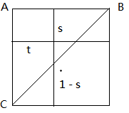
然后要根据s和t值,判断摄像机在row,col和row+1,col+1围成的四边形的哪个三角形上。如图所示,如果t < 1-s,则摄像机在上面一个三角形表面上,否则在下一个三角形表面上。
然后计算三角ABC两边的向量AC(Xc–Xa,Yc-Ya,Zc-Za)和AB(Xb–Xa,Yb-Ya,Zb-Za),那么摄像机的位置相对于顶点A的位移就为s * AB + s * AC。我们这里只关心Y值,所以,获取三个顶点A,B,C的高度值,即可计算出摄像机的高度值。如果在下面一个三角形上,计算方法类似。具体代码如下。
float Terrain::getHeight(float x, float z)
{
	// Transform from terrain local space to "cell" space.
	float c = (x + 0.5f*mWidth) /  mDX;
	float d = (z - 0.5f*mDepth) / -mDZ;

	// Get the row and column we are in.
	int row = (int)floorf(d);
	int col = (int)floorf(c);

	// Grab the heights of the cell we are in.
	// A*--*B
	//  | /|
	//  |/ |
	// C*--*D
	float A = mHeightmap(row, col);
	float B = mHeightmap(row, col+1);
	float C = mHeightmap(row+1, col);
	float D = mHeightmap(row+1, col+1);

	// Where we are relative to the cell.
	float s = c - (float)col;
	float t = d - (float)row;

	// If upper triangle ABC.
	if(t < 1.0f - s)
	{
		float uy = B - A;
		float vy = C - A;
		return A + s*uy + t*vy;
	}
	else // lower triangle DCB.
	{
		float uy = C - D;
		float vy = B - D;
		return D + (1.0f-s)*uy + (1.0f-t)*vy;
	}
}
如何摄像机的移动方向是平行于xz平面的,那么通过调整摄像机高度y值后,摄像机的移动速度将不再恒定。因此需要根据地形高度调整摄像机的移动方法。方法是,在一个时间点上,摄像机的移动方向是摄像机的look方法,在地形上的位置为P0。取得按这个方向移动一定距离后的点对应的地形高度值Y即得到这个点投影到地形上的点P。那么摄像机在地形表面移动的瞬时地形切线向量就为P-P0。具体代码如下。
// Find the net direction the camera is traveling in (since the
// camera could be running and strafing).
D3DXVECTOR3 dir(0.0f, 0.0f, 0.0f);
if( g_input->keyDown(DIK_W) )
	dir += mLookW;
if( g_input->keyDown(DIK_S) )
	dir -= mLookW;
if( g_input->keyDown(DIK_D) )
	dir += mRightW;
if( g_input->keyDown(DIK_A) )
	dir -= mRightW;

// Move at mSpeed along net direction.
D3DXVec3Normalize(&dir, &dir);
D3DXVECTOR3 newPos = mPosW + dir*mSpeed*dt;

if( terrain != 0)
{
	// New position might not be on terrain, so project the
	// point onto the terrain.
	newPos.y = terrain->getHeight(newPos.x, newPos.z) + offsetHeight;

	// Now the difference of the new position and old (current)
	// position approximates a tangent vector on the terrain.
	D3DXVECTOR3 tangent = newPos - mPosW;
	D3DXVec3Normalize(&tangent, &tangent);

	// Now move camera along tangent vector.
	mPosW += tangent*mSpeed*dt;

	// After update, there may be errors in the camera height since our
	// tangent is only an approximation.  So force camera to correct height,
	// and offset by the specified amount so that camera does not sit
	// exactly on terrain, but instead, slightly above it.
	mPosW.y = terrain->getHeight(mPosW.x, mPosW.z) + offsetHeight;
}
else
{
	mPosW = newPos;
}
最终效果
本文的例子和代码参考《Introduction to 3D Game Programming with DirectX 9.0c—A Shader Approach》第17章Terrain Rendering ,有兴趣的同学可以阅读原文。
完整的代码请访问GoogleCode,使用你最喜欢的SVN客户端下载。
http://d3dexamples.googlecode.com/svn/trunk/
作者: devj 发表于 2011-10-18 11:47 原文链接
最新新闻:
· 苹果周二发布第三季度财报 iPhone成信心保障(2011-10-18 20:46)
· 求解斯芬克斯之谜——《X光下看腾讯》序(2011-10-18 20:44)
· 预告:Android 4.0 将于明日香港首发(2011-10-18 20:39)
· Twitter活跃用户量超1亿 超50%用户每天登陆(2011-10-18 20:36)
· 调查称近八成人每天必登录Facebook(2011-10-18 20:33)


